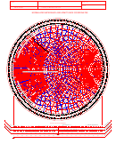
Although Smith did a great deal of work with antennas, his expertise and passion focused on transmission lines.


In 1928, he joined Bell Labs, where he became involved in the design of antennas for commercial AM broadcasting. Smith attended Tufts College and was an active amateur radio operator with the callsign 1ANB. The Smith Chart was invented by Phillip Smith, who was born in Lexington, MA on April 29, 1905. After reading this, you will have a better understanding of impedance matching and VSWR - common parameters in a radio station. The purpose of this article is to introduce you to the basics of the Smith Chart. Coined and developed by Paul Smith, smith charts were essentially deployed to provide electrical, microwave and electronic engineering solutions much before the advent of digital computers.The Smith Chart is one of the most useful tools in radio communications, but it is often misunderstood. The charts were brought to limelight in the wake of World War II to evaluate the problems associated with the transmission of radio waves.Ī Smith chart can largely be identified as a diagrammatic illustration revolving around the behavior of transmission lines. It can be most importantly touted as a graphical tool or calculator that assists in displaying and understanding the impedance and frequency values associated with transmission lines with the help of equations. The chart was acknowledged as a transmission line calculator owing to its prime purpose of use. Gradually, the charts were effectively opted for various other parameters to visualize as well as analyze complexities of functions to derive accuracy and productivity in results.

Smith charts play an integral part to evaluate the impedance values of transmission lines in circuits associated with high frequency. The chart is a basically circular structure constituting of two major circles or arcs, namely the Constant R Circles and the Constant X Circles that help to visually define the shape and the data values incorporated in the chart. In simple terms, the graph can be considered a collection of circles, where each of the circle is placed at different locations in the plot area. Each of the circular structure either denotes the constant resistance or constant reactance.


 0 kommentar(er)
